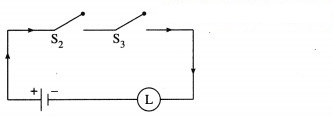
Question 1.
Express the following circuits in the symbolic form of logic and writ the input-output table.
(i)
Solution:
Let p : the switch S1 is closed
q : the switch S2 is closed
r : the switch S3 is closed
~p : the switch S1‘ is closed or the switch S1is open
~q : the switch S2‘ is closed or the switch S2 is open
~r : the switch S3‘ is closed or the switch S3 is open
l : the lamp L is on
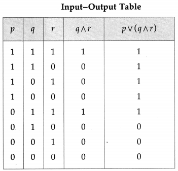
(i) The symbolic form of the given circuit is : p ∨ (q ∧ r) = l
l is generally dropped and it can be expressed as : p ∨ (q ∧ r).
(ii)
Solution:
The symbolic form of the given circuit is : (~ p ∧ q) ∨ (p ∧ ~ q).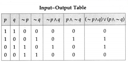
(iii)
Solution:
The symbolic form of the given circuit is : [p ∧ (~q ∨ r)] ∨ (~q ∧ ~ r).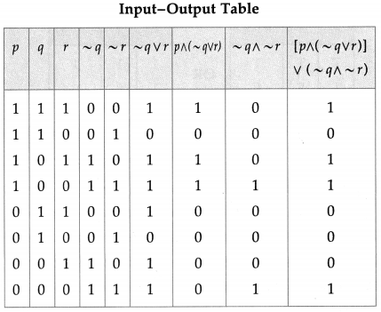
(iv)
Solution:
The symbolic form of the given circuit is : (p ∨ q) ∧ q ∧ (r ∨ ~p).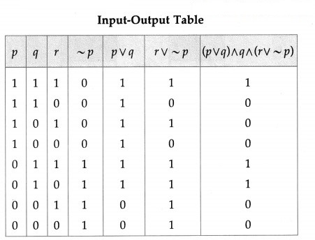
(v)
Solution:
The symbolic form of the given circuit is : [p ∨ (~p ∧ ~q)] ∨ (p ∧ q).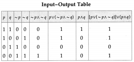
(vi)
Solution:
The symbolic form of the given circuit is : (p ∨ q) ∧ (q ∨ r) ∧ (r ∨ p)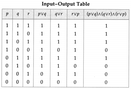
Question 2.
Construct the switching circuit of the following :
(i) (~p∧ q) ∨ (p∧ ~r)
Solution:
Let p : the switch S1 is closed
q : the switch S2 is closed
r : the switch S3 is closed
~p : the switch S1‘ is closed or the switch S1 is open
~ q : the switch S2‘ is closed or the switch S2 is open
~ r : the switch S3‘ is closed or the switch S3 is open.
Then the switching circuits corresponding to the given statement patterns are :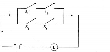
(ii) (p∧ q) ∨ [~p ∧ (~q ∨ p ∨ r)]
Solution:
(iii) [(p ∧ r) ∨ (~q ∧ ~r)] ∧ (~p ∧ ~r)
Solution:
(iv) (p ∧ ~q ∧ r) ∨ [p ∧ (~q ∨ ~r)]
Solution:
(v) p ∨ (~p ) ∨ (~q) ∨ (p ∧ q)
Solution:
(vi) (p ∧ q) ∨ (~p) ∨ (p ∧ ~q)
Solution:
Question 3.
Give an alternative equivalent simple circuits for the following circuits :
(i)
Solution:
(i) Let p : the switch S1 is closed
q : the switch S2 is closed
~ p : the switch S1‘ is closed or the switch Si is open Then the symbolic form of the given circuit is :
p ∧ (~p ∨ q).
Using the laws of logic, we have,
p ∧ (~p ∨ q)
= (p ∧ ~ p) ∨ (p ∧ q) …(By Distributive Law)
= F ∨ (p ∧ q) … (By Complement Law)
= p ∧ q… (By Identity Law)
Hence, the alternative equivalent simple circuit is :
(ii)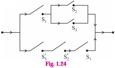
Let p : the switch S1 is closed
q : the switch S2 is closed
r : the switch S3 is closed
~q : the switch S2‘ is closed or the switch S2 is open
~r : the switch S3‘ is closed or the switch S3 is open.
Then the symbolic form of the given circuit is :
[p ∧ (q ∨ r)] ∨ (~r ∧ ~q ∧ p).
Using the laws of logic, we have
[p ∧ (q ∨ r)] ∨ (~r ∧ ~q ∧ p)
≡ [p ∧ (q ∨ r)] ∨ [ ~(r ∨ q) ∧ p] …. (By De Morgan’s Law)
≡ [p ∧ (q ∨ r)] ∨ [p ∧ ~(q ∨ r)] … (By Commutative Law)
≡ p ∧ [(q ∨ r) ∨ ~(q ∨ r)) … (By Distributive Law)
≡ p ∧ T … (By Complement Law)
≡ p … (By Identity Law)
Hence, the alternative equivalent simple circuit is :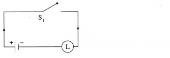
Question 4.
Write the symbolic form of the following switching circuits construct its switching table and interpret it.
i)
Solution:
Let p : the switch S1 is closed
q : the switch S2 is closed
~p : the switch S1‘ is closed or the switch S1 is open
~ q : the switch S2‘ is closed or the switch S2 is open.
Then the symbolic form of the given circuit is :
(p ∨ ~q) ∨ (~p ∧ q)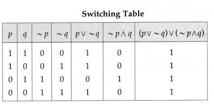
Since the final column contains all’ 1′, the lamp will always glow irrespective of the status of switches.
(ii)
Solution:
Let p : the switch S1 is closed
q : the switch S2 is closed
~p : the switch S1 is closed or the switch S1 is open.
~q : the switch S2‘ is closed or the switch S2 is open.
Then the symbolic form of the given circuit is : p ∨ (~p ∧ ~q) ∨ (p ∧ q)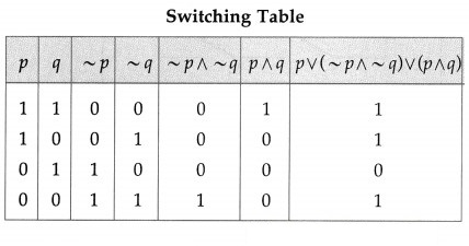
Since the final column contains ‘0’ when p is 0 and q is ‘1’, otherwise it contains ‘1′.
Hence, the lamp will not glow when S1 is OFF and S2 is ON, otherwise the lamp will glow.
iii)
Solution:
Let p : the switch S1 is closed
q : the switch S2 is closed
r : the switch S3 is closed
~q : the switch S2‘ is closed or the switch S2 is open
~r: the switch S3‘ is closed or the switch S3 is open.
Then the symbolic form of the given circuit is : [p ∨ (~q) ∨ r)] ∧ [p ∨ (q ∧ r)]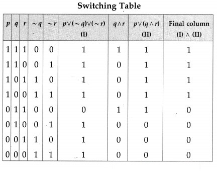
From the switching table, the ‘final column’ and the column of p are identical. Hence, the lamp will glow which S1 is ‘ON’.
Question 5.
Obtain the simple logical expression of the following. Draw the corresponding switching circuit.
(i) p ∨ (q ∧ ~ q)
Solution:
Using the laws of logic, we have, p ∨ (q ∧ ~q)
≡ p ∨ F … (By Complement Law)
≡ p … (By Identity Law)
Hence, the simple logical expression of the given expression is p.
Let p : the switch S1 is closed
Then the corresponding switching circuit is :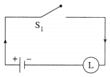
(ii) (~p ∧ q) ∨ (~p ∧ ~q) ∨ (p ∧ ~q)]
Solution:
Using the laws of logic, we have,
(~p ∧ q) ∨ (~p ∨ ~q) ∨ (p ∧ ~q)
≡ [~p ∧ (q ∨ ~q)] ∨ (p ∧ ~ q)… (By Distributive Law)
≡ (~p ∧ T) ∨ (p ∧ ~q) … (By Complement Law)
≡ ~p ∨ (p ∧ ~q) … (By Identity Law)
≡ (~p ∨ p) ∧ (~p ∧~q) … (By Distributive Law)
≡ T ∧ (~p ∧ ~q) … (By Complement Law)
≡ ~p ∨ ~q … (By Identity Law)
Hence, the simple logical expression of the given expression is ~ p ∨ ~q.
Let p : the switch S1 is closed
q : the switch S2 is closed
~ p : the switch S1‘ is closed or the switch S1 is open
~ q : the switch S2‘ is closed or the switch S2 is open,
Then the corresponding switching circuit is :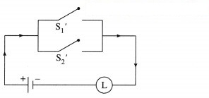
(iii) [p (∨ (~q) ∨ ~r)] ∧ (p ∨ (q ∧ r)
Solution:
Using the laws of logic, we have,
[p ∨ (~ (q) ∨ (~r)] ∧ [p ∨ (q ∧ r)]
= [p ∨ { ~(q ∧ r)}] ∧ [p ∨ (q ∧ r)] … (By De Morgan’s Law)
= p ∨ [~(q ∧ r) ∧ (q ∧ r) ] … (By Distributive Law)
= p ∨ F … (By Complement Law)
= p … (By Identity Law)
Hence, the simple logical expression of the given expression is p.
Let p : the switch S1 is closed
Then the corresponding switching circuit is :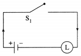
(iv) (p ∧ q ∧ ~p) ∨ (~p ∧ q ∧ r) ∨ (p ∧ ~q ∧ r) ∨ (p ∧ q ∧ r)
Question is Modified
(p ∧ q ∧ ~p) ∨ (~p ∧ q ∧ r)∨ (p ∧ q ∧ r)
Solution:
Using the laws of logic, we have,
(p ∧ q ∧ ~p) ∨ (~p ∧ q ∧ r) ∨ (p ∧ q ∧ r)
= (p ∧ ~p ∧ q) ∨ (~p ∧ q ∧ r) ∨ (p ∧ q ∧ r) … (By Commutative Law)
= (F ∧ q) ∨ (~p ∧ q ∧ r) ∨ (p ∧ q ∧ r) … (By Complement Law)
= F ∨ (~p ∧ q ∧ r) ∨ (p ∧ q ∧ r) … (By Identity Law)
= (~p ∧ q ∧ r) ∨ (p ∧ q ∧ r) … (By Identity Law)
= (~ p ∨ p) ∧ (q ∧ r) … (By Distributive Law)
= T ∧ (q ∧ r) … (By Complement Law)
= q ∧ r … (By Identity Law)
Hence, the simple logical expression of the given expression is q ∧ r.
Let q : the switch S2 is closed
r : the switch S3 is closed.
Then the corresponding switching circuit is :